

Cable Glands & Shield Termination: 360° EMC Termination
A braided shield only does its job if the braid is bonded to the enclosure around its full circumference. Twist it into a pigtail and, at the switching frequencies of a VFD or a servo drive, it is barely a shield at all. This guide shows what 360° termination means in practice, which gland or clamp to use, and how it applies to the shielded cables in our range — from BPYJVP drive cables to servo, TRVVP and LiYCY.
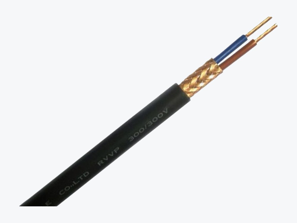
1. What 360° termination means
The braid is a tube, not a wire. In a 360° termination the braid is folded back over the full circumference and gripped by the EMC gland’s contact ring — or pressed flat under a shield clamp on the gland plate — so high-frequency current has a low-impedance path all the way round, and the shield continues into the enclosure instead of stopping at it.
A pigtail does the opposite: it gathers the braid into one thin twisted wire to a terminal. The impedance of that wire rises exactly at the frequencies where the shield has to work, and the centimetres of unshielded core past the braid become an antenna. Keep unshielded tails as short as possible — strip back only what the gland needs.
360° means the braid meets the enclosure around its full circumference — EMC gland or shield clamp, at both ends, never a pigtail. The gland is sized from the cable’s outer diameter, and every construction in our selector publishes its OD, so gland size and cabinet entry can be planned before ordering.
2. Three ways to end a shield
| Method | How it works | Use it when | Watch out |
|---|---|---|---|
| EMC gland | A conductive gland whose contact ring grips the exposed braid around the full circumference as the cable enters the enclosure | Cabinet or motor terminal-box entry; VFD and servo duty | The gland bore must match the cable OD — read the OD from the selector row |
| Shield clamp on a gland plate | A metal clamp presses the exposed braid flat against the earthed gland plate | Drive cabinets with a gland plate; several cables side by side | The plate itself must be bonded to the cabinet earth |
| Pigtail (twisted drain wire) | The braid is gathered and twisted into a single wire to a terminal | Only where the instrument maker calls for it, on a legacy low-frequency loop | At switching frequencies it is barely a shield — never for VFD or servo duty |
We supply the cable, not the gland: the gland follows the enclosure standard and the drive maker’s EMC instructions. What we publish — the shield construction and the outer diameter of every row — is what sizes it.
3. Which of our cables need it
Every shielded family in our range is built to be terminated this way. The table lists the shield each family carries, with selector counts recomputed from our data.
| Family | Shield | Selector rows | Outer diameter |
|---|---|---|---|
| BPYJVP — VFD motor cable | Copper tape + copper braid, 80% coverage | 15 | 12.0–59.0 mm |
| Servo SERVO-CY family | Overall copper braid; brake pair separately shielded | 184 | 12.0–32.0 mm |
| TRVVP drag chain | Tinned-copper braid | 1,483 | 4.6–61.1 mm |
| TRVVSP drag chain | Braid + cores twisted in pairs | 300 | 6.5–31.0 mm |
| LiYCY data cable | Copper braid | 471 | 4.1–30.0 mm |
BPYJVP carries a dual shield — an inner copper tape wrap for continuous electrostatic coverage and an outer copper wire braid (80% coverage density) that carries the high-frequency currents — around XLPE insulation, rated 0.6/1 kV with Class 5 flexible conductors. The servo family adds a separately shielded brake pair, (2 × 0.5)P and up, feeding the motor’s 24 V DC holding brake. The fixed-installation shielded group in the selector holds 32,627 constructions — RVVP, ZR-RVVP, RVVSP and LiYCY among them — each with its outer diameter published, so gland size and cabinet entry can be planned before ordering.
How the families differ is covered in our guides to servo motor cables, VFD 3+3 shielding and TRVV vs TRVVP vs TRVVSP.
4. Both ends or one end?
| Duty | Terminate | Why |
|---|---|---|
| VFD motor cable (BPYJVP) | Both ends, 360° | The shield is a high-frequency return path; single-end termination defeats it at switching frequencies |
| Servo power + brake pair | Both ends, 360° | Floating or single-end shields do not control high-frequency coupling |
| Drag chain TRVVP / TRVVSP | Both ends, 360° | The chain runs past drives; the shield must be continuous end to end |
| Data / measurement (LiYCY) | Both ends, 360° | For high-frequency interference, bond at both ends |
| Legacy low-frequency analog loop | Follow the instrument maker — single-end where it calls for it | Avoids ground-loop currents at low frequencies |
Two rules hold for every row. Do not use the shield as the protective earth — BPYJVP carries three dedicated earth conductors, and the shield is an EMC component. And keep the shield continuous: avoid joints, and where one is unavoidable, maintain full-circumference shield continuity through the enclosure.
5. Real selector rows: six shielded sizes
Six real stock sizes from our cable selector — stock code, model, construction, outer diameter and weight. The outer diameter is the number the gland is sized from:
| Stock code | Model | Construction | Outer dia. | Weight |
|---|---|---|---|---|
| C283010005010 | RVVP | 0.5×10C | 10.0 mm | 163 kg/km |
| C296080005010 | ZR-RVVP (105 °C) | 0.5×10C | 10.0 mm | 163 kg/km |
| C101040005010 | LiYCY | 0.5×10C | 9.9 mm | 151 kg/km |
| H102030005010 | TRVVP | 0.50×10C | 11.0 mm | 208 kg/km |
| S101011000301503 | BPYJVP | 3×10+3×1.5 | 17.0 mm | 554 kg/km |
| L102010150400501 | SERVO-CY | 4 × 1.5 + (2 × 0.5)P | 13.0 mm | 224 kg/km |
Find your exact size in the cable selector, or browse the drag chain cable range.
6. Mistakes that undo the shield
| Mistake | What it causes | Fix |
|---|---|---|
| Pigtail instead of 360° | Shield impedance rises at switching frequencies; drive trips, encoder faults | EMC gland or shield clamp, braid over the full circumference |
| Single-end termination on VFD or servo | High-frequency return path broken; emissions and bearing currents | Terminate both ends, 360° |
| Long unshielded tail past the gland | Exposed cores radiate and pick up noise | Strip back only what the gland needs; keep tails short |
| Shield used as protective earth | Fault current through the braid; EMC and safety both compromised | Use the dedicated earth conductors (BPYJVP 3+3) |
| Shield broken at a joint or connector | The screen stops at the break; noise enters there | Maintain full-circumference continuity through the enclosure |
| Gland sized from guesswork, not OD | Braid not gripped, or the cable crushed | Size from the published OD of your exact selector row |
Installation practice for the chain itself — bend radius, slack and separators — is in our drag chain cable installation guide.
Frequently asked questions
- What does 360° termination mean?
- The braid is bonded to the enclosure around its full circumference — folded back onto an EMC gland’s contact ring, or pressed under a shield clamp on the gland plate — so high-frequency current has a low-impedance path all the way round. A twisted pigtail is not 360° termination.
- Do I terminate the shield at one end or both?
- Both ends, 360°, for VFD, servo, drag-chain and data cables carrying high-frequency interference. The one exception is a legacy low-frequency analog loop where the instrument maker calls for single-end bonding to avoid ground-loop currents.
- Which gland fits my cable?
- The gland is sized from the cable’s outer diameter. Every construction in our selector publishes its OD — find your row, read the OD, and size the gland bore to it.
- Can I use a standard gland instead of an EMC gland?
- A standard gland seals and grips the cable, but it does not bond the braid around the circumference — the shield then ends at the gland instead of continuing into the enclosure. For VFD and servo duty, use an EMC gland or a shield clamp on the gland plate.
- What if my construction is not in the selector?
- Send the cores, the shielding, the outer diameter and the length. Custom builds start at 300 m, and we usually quote within one working day.
Send the cable type, the OD and the cabinet entry
Send the cable, its outer diameter and where it enters the cabinet — drive and motor data for VFD and servo runs. We will confirm the gland size and the termination, and quote usually within one working day.
Cable Selector WhatsApp Request a Quote